Skip to content

clements

The quotonic.clements module includes a class that allows Mach-Zehnder interferometer (MZI) meshes arranged in the Clements configuration to be instantiated. For each instance, the user may optionally provide values to quantify experimental imperfections including photon propagation losses and/or imbalanced directional coupler splitting ratios. Once instantiated, the user may supply a linear unitary transformation that is then decomposed into phase shifts, or alternatively provide phase shifts to encode a linear unitary (non-unitary if imperfect) transformation. Note that the code has been designed to produce accurate representations of \(2\times 2\) meshes (i.e. a single MZI followed by 2 output phase shifts), however, the documentation corresponds to cases where \(m > 2\).

The code in this module has been inspired by the encoding proposed in W. R. Clements et al., "Optimal design for universal multiport interferometers", Optica 3, 1460-1465 (2016), and its python implementations in both Bosonic: A Quantum Optics Library, as originally designed for use in G. R. Steinbrecher et al., “Quantum optical neural networks”, npj Quantum Inf 5, 60 (2019), and Cascaded Optical Systems Approach to Neural Networks (CasOptAx) as originally designed for use in J. R. Basani et al., "Universal logical quantum photonic neural network processor via cavity-assisted interactions", npj Quantum Inf 11, 142 (2025).

Mesh

Mesh of Mach-Zehnder interferometers arranged in the Clements configuration.

Each mesh of Mach-Zehnder interferometers (MZIs) is classified by a number of optical modes \(m\). Also, fabrication imperfections can optionally be modelled by providing the percentage propagation losses for each MZI and phase shifter, and/or the imbalanced splitting ratios of each nominally 50:50 directional coupler.

This class features methods to compute the matrix representation (only unitary when lossless) of a mesh from MZI and output phase shifts, as well as decompose a matrix representation to identify the MZI and output phase shifts required to realize it. This decomposition follows the scheme of Clements et al. (cited above), yet has been adjusted to work with the MZI transfer matrix associated with integrated photonic circuits (see decode for more details).

Attributes:

Name Type Description
m int

number of optical modes, \(m\)

ell_mzi jnp_ndarray

\(m\times m\) array containing the percentage loss per arm of the interferometer mesh, for each column of MZIs respectively

ell_ps jnp_ndarray

\(m\)-length array containing the percentage loss for each of the output phase shifters

t_dc jnp_ndarray

\(2\times m(m-1)/2\) array containing the splitting ratio (T:R) of each directional coupler in the mesh, organized such that each column corresponds to one MZI, the top row being the first directional coupler and the bottom being the second, where the MZIs are ordered from top to bottom followed by left to right across the mesh

Source code in src/quotonic/clements.py
 29
 30
 31
 32
 33
 34
 35
 36
 37
 38
 39
 40
 41
 42
 43
 44
 45
 46
 47
 48
 49
 50
 51
 52
 53
 54
 55
 56
 57
 58
 59
 60
 61
 62
 63
 64
 65
 66
 67
 68
 69
 70
 71
 72
 73
 74
 75
 76
 77
 78
 79
 80
 81
 82
 83
 84
 85
 86
 87
 88
 89
 90
 91
 92
 93
 94
 95
 96
 97
 98
 99
100
101
102
103
104
105
106
107
108
109
110
111
112
113
114
115
116
117
118
119
120
121
122
123
124
125
126
127
128
129
130
131
132
133
134
135
136
137
138
139
140
141
142
143
144
145
146
147
148
149
150
151
152
153
154
155
156
157
158
159
160
161
162
163
164
165
166
167
168
169
170
171
172
173
174
175
176
177
178
179
180
181
182
183
184
185
186
187
188
189
190
191
192
193
194
195
196
197
198
199
200
201
202
203
204
205
206
207
208
209
210
211
212
213
214
215
216
217
218
219
220
221
222
223
224
225
226
227
228
229
230
231
232
233
234
235
236
237
238
239
240
241
242
243
244
245
246
247
248
249
250
251
252
253
254
255
256
257
258
259
260
261
262
263
264
265
266
267
268
269
270
271
272
273
274
275
276
277
278
279
280
281
282
283
284
285
286
287
288
289
290
291
292
293
294
295
296
297
298
299
300
301
302
303
304
305
306
307
308
309
310
311
312
313
314
315
316
317
318
319
320
321
322
323
324
325
326
327
328
329
330
331
332
333
334
335
336
337
338
339
340
341
342
343
344
345
346
347
348
349
350
351
352
353
354
355
356
357
358
359
360
361
362
363
364
365
366
367
368
369
370
371
372
373
374
375
376
377
378
379
380
381
382
383
384
385
386
387
388
389
390
391
392
393
394
395
396
397
398
399
400
401
402
403
404
405
406
407
408
409
410
411
412
413
414
415
416
417
418
419
420
421
422
423
424
425
426
427
428
429
430
431
432
433
434
435
436
437
438
439
440
441
442
443
444
445
446
447
448
449
450
451
452
453
454
455
456
457
458
459
460
461
462
463
464
465
466
467
468
469
470
471
472
473
474
475
476
477
478
479
480
481
482
483
484
485
486
487
488
489
490
491
492
493
494
495
496
497
498
499
500
501
502
503
504
505
506
507
508
509
510
511
512
513
514
515
516
517
518
519
520
521
522
523
524
525
526
527
528
529
530
531
532
533
534
535
536
537
538
539
540
541
542
543
544
545
546
547
548
549
550
551
552
553
554
555
556
557
class Mesh:
    """Mesh of Mach-Zehnder interferometers arranged in the Clements configuration.

    Each mesh of Mach-Zehnder interferometers (MZIs) is classified by a number of optical modes $m$.
    Also, fabrication imperfections can optionally be modelled by providing the percentage propagation losses for
    each MZI and phase shifter, and/or the imbalanced splitting ratios of each nominally 50:50 directional coupler.

    This class features methods to compute the matrix representation (only unitary when lossless) of a mesh from MZI and
    output phase shifts, as well as decompose a matrix representation to identify the MZI and output phase shifts
    required to realize it. This decomposition follows the scheme of Clements *et al*. (cited above), yet has been
    adjusted to work with the MZI transfer matrix associated with integrated photonic circuits (see `decode` for
    more details).

    Attributes:
        m (int): number of optical modes, $m$
        ell_mzi (jnp_ndarray): $m\\times m$ array containing the percentage loss per arm of the interferometer mesh,
            for each column of MZIs respectively
        ell_ps (jnp_ndarray): $m$-length array containing the percentage loss for each of the output phase shifters
        t_dc (jnp_ndarray): $2\\times m(m-1)/2$ array containing the splitting ratio (T:R) of each directional
            coupler in the mesh, organized such that each column corresponds to one MZI, the top row being the first
            directional coupler and the bottom being the second, where the MZIs are ordered from top to bottom
            followed by left to right across the mesh
    """

    def __init__(
        self,
        m: int,
        ell_mzi: np_ndarray | None = None,
        ell_ps: np_ndarray | None = None,
        t_dc: np_ndarray | None = None,
    ) -> None:
        """Initialization of a Mach-Zehnder interferometer mesh arranged in the Clements configuration.

        Args:
            m: number of optical modes, $m$
            ell_mzi: $m\\times m$ array containing the percentage loss per arm of the interferometer mesh,
                for each column of MZIs respectively
            ell_ps: $m$-length array containing the percentage loss for each of the output phase shifters
            t_dc: $2\\times m(m-1)/2$ array containing the splitting ratio (T:R) of each directional coupler in the
                mesh, organized such that each column corresponds to one MZI, the top row being the first
                directional coupler and the bottom being the second, where the MZIs are ordered from top to bottom
                followed by left to right across the mesh
        """

        # fill in missing mesh properties
        if ell_mzi is None:
            ell_mzi = np.zeros((m, m), dtype=float)
        if ell_ps is None:
            ell_ps = np.zeros(m, dtype=float)
        if t_dc is None:
            t_dc = 0.5 * np.ones((2, m * (m - 1) // 2), dtype=float)

        # check the validity of the provided properties
        assert m > 1, "Cannot create any kind of interferometer with less than 2 modes"
        assert (ell_mzi.shape[0] == ell_mzi.shape[1]) and (
            ell_mzi.shape[0] == m
        ), "Loss per arm of the interferometer mesh must take the form of an m x m array"
        assert len(ell_ps) == m, "Loss per output phase shifter in the mesh must be an m-length array"
        assert (t_dc.shape[0] == 2) and (
            t_dc.shape[1] == m * (m - 1) // 2
        ), "Directional coupler splitting ratios (T:R) must be passed as a 2 x m(m-1)/2 array"

        # store the properties of the mesh internally
        self.m = m
        self.ell_mzi = jnp.asarray(ell_mzi)
        self.ell_ps = jnp.asarray(ell_ps)
        self.t_dc = jnp.asarray(t_dc)

    @partial(jit, static_argnums=(0,))
    def mzi(
        self,
        phi: float,
        theta: float,
    ) -> jnp_ndarray:
        """Construct $2\\times 2$ *ideal* Mach-Zehnder interferometer transfer matrix.

        The transfer matrix is defined as,

        $$ \\mathbf{T}_\\mathrm{mzi} = ie^{i\\theta}\\begin{pmatrix} e^{i\\phi}\\sin{\\theta} & \\cos{\\theta}
        \\\\ e^{i\\phi}\\cos{\\theta} & -\\sin{\\theta} \\end{pmatrix}, $$

        in the ideal case. See `encode` for further details.

        Args:
            phi: phase shift $\\phi$, in radians
            theta: phase shift $\\theta$, in radians

        Returns:
            A $2\\times 2$ complex 2D array representation of the ideal Mach-Zehnder interferometer transfer matrix
        """
        T00 = jnp.exp(1j * phi) * jnp.sin(theta)
        T01 = jnp.cos(theta)
        T10 = jnp.exp(1j * phi) * jnp.cos(theta)
        T11 = -jnp.sin(theta)
        return 1j * jnp.exp(1j * theta) * jnp.array([[T00, T01], [T10, T11]])

    @partial(jit, static_argnums=(0,))
    def mzi_inv(
        self,
        phi: float,
        theta: float,
    ) -> jnp_ndarray:
        """Construct $2\\times 2$ inverse of an *ideal* Mach-Zehnder interferometer transfer matrix.

        The inverse of the transfer matrix is defined as,

        $$ \\mathbf{T}_\\mathrm{mzi}^\\dagger = -ie^{-i\\theta}\\begin{pmatrix} e^{-i\\phi}\\sin{\\theta} & e^{-i\\phi}
        \\cos{\\theta} \\\\ \\cos{\\theta} & -\\sin{\\theta} \\end{pmatrix}, $$

        in the ideal case. See `encode` for further details.

        Args:
            phi: phase shift $\\phi$, in radians
            theta: phase shift $\\theta$, in radians

        Returns:
            A $2\\times 2$ complex 2D array representation of the inverse of the ideal Mach-Zehnder interferometer
                transfer matrix
        """
        T00 = jnp.exp(-1j * phi) * jnp.sin(theta)
        T01 = jnp.exp(-1j * phi) * jnp.cos(theta)
        T10 = jnp.cos(theta)
        T11 = -jnp.sin(theta)
        return -1j * jnp.exp(-1j * theta) * jnp.array([[T00, T01], [T10, T11]])

    @partial(jit, static_argnums=(0,))
    def encode(
        self,
        phi: jnp_ndarray,
        theta: jnp_ndarray,
        delta: jnp_ndarray,
    ) -> jnp_ndarray:
        """Encode a Mach-Zehnder interferometer mesh in the Clements configuration from an array of phase shifts.

        Each Mach-Zehnder interferometer (MZI), as displayed below, consists of two phase shifters enacting respective
        phase shifts $\\phi$, $\\theta$, and two directional couplers with respective splitting ratios $t_1$,
        $t_2$ (ideally, $t_1 = t_2 = 0.5$).

        <p align="center">
        <img width="500" src="../img/light/mzi.png" class="only-light">
        <img width="500" src="../img/dark/mzi.png" class="only-dark">
        </p>

        The phase shifter transfer matrices are given by,

        $$ \\mathbf{T}_\\mathrm{ps}(\\phi) = \\begin{pmatrix} e^{i\\phi} & 0 \\\\ 0 & 1 \\end{pmatrix} \\qquad\\qquad
        \\mathbf{T}_\\mathrm{ps}(2\\theta) = \\begin{pmatrix} e^{i2\\theta} & 0 \\\\ 0 & 1 \\end{pmatrix}, $$

        for phase shifts $\\phi$ and $2\\theta$ respectively. The directional coupler transfer matrix is given by,

        $$ \\mathbf{T}_\\mathrm{dc}(t) = \\begin{pmatrix} \\sqrt{t} & i\\sqrt{1-t} \\\\ i\\sqrt{1-t} & \\sqrt{t}
        \\end{pmatrix}, $$

        which simplifies to,

        $$ \\mathbf{T}_\\mathrm{dc}(0.5) = \\frac{1}{\\sqrt{2}}\\begin{pmatrix} 1 & i \\\\ i & 1 \\end{pmatrix}, $$

        in the ideal case of $t = 0.5$ (i.e. 50:50). Each MZI may contribute an imbalanced probability of photon loss
        in each of its arms. This is modelled by multiplying a loss matrix,

        $$ \\mathbf{T}_\\mathrm{loss}(\\alpha_\\mathrm{up}, \\alpha_\\mathrm{low}) = \\begin{pmatrix}
        \\sqrt{1 - \\alpha_\\mathrm{up}} & 0 \\\\ 0 & \\sqrt{1 - \\alpha_\\mathrm{low}} \\end{pmatrix}, $$

        where $\\alpha_\\mathrm{up}$, $\\alpha_\\mathrm{low}$ are the fractions of light lost in the upper and lower
        arms of the MZI, respectively. Altogether, the MZI transfer matrix is given by,

        $$ \\mathbf{T}_\\mathrm{mzi} = \\mathbf{T}_\\mathrm{loss}(\\alpha_\\mathrm{up}, \\alpha_\\mathrm{low})
        \\mathbf{T}_\\mathrm{dc}(t_2) \\mathbf{T}_\\mathrm{ps}(2\\theta) \\mathbf{T}_\\mathrm{dc}(t_1)
        \\mathbf{T}_\\mathrm{ps}(\\phi) = \\begin{pmatrix} \\sqrt{1 - \\alpha_\\mathrm{up}} & 0 \\\\ 0 & \\sqrt{1 -
        \\alpha_\\mathrm{low}} \\end{pmatrix} \\begin{pmatrix} \\sqrt{t_2} & i\\sqrt{1-t_2} \\\\ i\\sqrt{1-t_2} &
        \\sqrt{t_2} \\end{pmatrix} \\begin{pmatrix} e^{i2\\theta} & 0 \\\\ 0 & 1 \\end{pmatrix} \\begin{pmatrix}
        \\sqrt{t_1} & i\\sqrt{1-t_1} \\\\ i\\sqrt{1-t_1} & \\sqrt{t_1} \\end{pmatrix} \\begin{pmatrix} e^{i\\phi} & 0
        \\\\ 0 & 1 \\end{pmatrix}, $$

        which simplifies to,

        $$ \\mathbf{T}_\\mathrm{mzi} = \\mathbf{T}_\\mathrm{loss}(0, 0)\\mathbf{T}_\\mathrm{dc}(0.5)
        \\mathbf{T}_\\mathrm{ps}(2\\theta) \\mathbf{T}_\\mathrm{dc}(0.5) \\mathbf{T}_\\mathrm{ps}(\\phi) =
        ie^{i\\theta} \\begin{pmatrix} e^{i\\phi}\\sin{\\theta} & \\cos{\\theta} \\\\ e^{i\\phi}\\cos{\\theta} &
        -\\sin{\\theta} \\end{pmatrix}, $$

        in the ideal case of $t_1 = t_2 = 0.5$, $\\alpha_\\mathrm{up} = \\alpha_\\mathrm{low} = 0$.

        Using Clements encoding, any $m\\times m$ unitary matrix can be generated by multiplying a set of block
        diagonal unitary transformations $\\mathbf{T}_{p,q}(\\phi,\\theta)$ with the $m\\times m$ identity matrix in a
        specific order. Each transformation, $\\mathbf{T}_{p,q}$, features a $2\\times 2$ block that acts only on
        adjacent modes $p,q : p = q-1$. This $2\\times 2$ block is computed according to MZI description above.
        Transformations, $\\mathbf{T}_{p,q}$, are applied in each iteration of the loop. When the loop counter is
        even, `m0 = 0` such that the transformations for the first two optical modes and each consecutive adjacent
        pair are generated. For example, if $m = 5$, then the initial iteration will generate and apply $\\mathbf{
        T}_{0,1}$, $\\mathbf{T}_{2,3}$, while the second iteration (`m0 = 1`) produces $\\mathbf{T}_{1,2}$,
        $\\mathbf{T}_{3,4}$. Since the phases are respectively input in 1D arrays, it must be accessed specifically
        when generating the transformations. Each phase shift column ($\\phi$ or $\\theta$) requires as many phase
        parameters as there are transformations to generate in a given loop iteration. Thus, the input array is
        accessed according to the column and depends on $m$ and `m0` for the particular iteration. The matrix
        multiplications take place according to the order (left to right) in the figure above, Therefore,
        as an example, if a given iteration constructs two transformations, $\\mathbf{T}_{0,1}$ and
        $\\mathbf{T}_{2,3}$, the phase shifts must be ordered as $\\phi_{0,1}$, $\\phi_{2,3}$ in the array
        `phi`, and $\\theta_{0,1}$, $\\theta_{2,3}$ in the array `theta`.

        By applying all transformations in the specified order, followed by a column of output phase shifters on
        each mode, a rectangular mesh that represents the full $m \\times m$ single-photon unitary matrix is
        generated. This is displayed below, where each cross is a MZI.

        <p align="center">
        <img width="500" src="../img/light/mesh.png" class="only-light">
        <img width="500" src="../img/dark/mesh.png" class="only-dark">
        </p>

        Mathematically, this procedure takes the form,

        $$ \\mathbf{U}(\\boldsymbol{\\phi}, \\boldsymbol{\\theta}) =
        \\mathbf{D}\\prod_{(p,q)\\in R}\\mathbf{T}_{p,q}(\\phi,\\theta), $$

        where $R$ is the sequence of the $\\frac{1}{2}m(m-1)$ two-mode transformations, $\\phi$, $\\theta$ are
        elements of the corresponding vectors $\\boldsymbol{\\phi}$, $\\boldsymbol{\\theta}$ that are selected
        according to the sequence, and $\\mathbf{D}$ is a diagonal $m\\times m$ matrix that is representative of the
        column of output phase shifters.

        It is termed a "single-photon" unitary as it is a representation only in the Fock basis of $m$ modes when $n
        = 1$. To obtain the "multi-photon" unitary, a transformation must be applied (see [aa](aa.md)).

        The code in this method is heavily inspired by [CasOptAx](https://github.com/JasvithBasani/CasOptAx), which is
        properly cited at the top of the page.

        Args:
            phi: $m(m-1)/2$ phase shifts, $\\boldsymbol{\\phi}$, for all MZIs in the mesh
            theta: $m(m-1)/2$ phase shifts, $\\boldsymbol{\\theta}$, for all MZIs in the mesh
            delta: $m$ phase shifts, $\\boldsymbol{\\delta}$, applied in each mode at the output of the mesh

        Returns:
            U: an $m\\times m$ 2D array representative of the linear unitary transformation,
                $\\mathbf{U}(\\boldsymbol{\\phi}, \\boldsymbol{\\theta}, \\boldsymbol{\\delta})$, enacted by the
                Clements mesh
        """

        # check the validity of the mesh and the provided phases
        assert self.m > 2, "Clements encoding is only relevant for m > 2, see 'mzi' otherwise"
        assert len(phi) == int(self.m * (self.m - 1) / 2), "There must be exactly m(m-1)/2 phi phase shifts"
        assert len(theta) == int(self.m * (self.m - 1) / 2), "There must be exactly m(m-1)/2 theta phase shifts"
        assert len(delta) == int(self.m), "There must be exactly m delta phase shifts"

        # ensure that the provided phases are jax arrays
        phi = jnp.asarray(phi)
        theta = jnp.asarray(theta)
        delta = jnp.asarray(delta)

        # iterate through each column of the mesh, constructing and multiplying the transformations for each MZI
        ind = 0
        m_2 = self.m // 2
        odd = self.m % 2  # equals 0 if even, 1 if odd
        even = (self.m + 1) % 2  # equals 0 if odd, 1 if even
        columns = []
        for col in range(self.m):
            # calculate whether MZIs should be inserted from mode 0 or mode 1
            m0 = col % 2

            # extract the parameters for the MZIs in this column
            theta_col = theta[ind : ind + m_2 - m0 * even]
            phi_col = phi[ind : ind + m_2 - m0 * even]
            t_dc_col = self.t_dc[:, ind : ind + m_2 - m0 * even]
            ind += m_2 - m0 * even

            # construct matrices that describe the transformations enacted by two full columns of T:R
            # directional couplers, nominally 50:50
            dc_diag = jnp.diag(
                jnp.pad(
                    jnp.repeat(jnp.sqrt(t_dc_col[0]), 2),
                    (m0, (m0 + odd) % 2),
                    "constant",
                    constant_values=(1.0, 1.0),
                )
            )
            dc_offdiag_up = jnp.roll(
                jnp.diag(
                    jnp.pad(
                        jnp.dstack(
                            (1j * jnp.sqrt(1.0 - t_dc_col[0]), jnp.zeros(m_2 - m0 * even, dtype=complex))
                        ).flatten(),
                        (m0, (m0 + odd) % 2),
                        "constant",
                        constant_values=(0.0, 0.0),
                    )
                ),
                1,
            )
            dc_offdiag_down = jnp.roll(
                jnp.diag(
                    jnp.pad(
                        jnp.dstack(
                            (jnp.zeros(m_2 - m0 * even, dtype=complex), 1j * jnp.sqrt(1.0 - t_dc_col[0]))
                        ).flatten(),
                        (m0, (m0 + odd) % 2),
                        "constant",
                        constant_values=(0.0, 0.0),
                    )
                ),
                -1,
            )
            dc1 = dc_diag + dc_offdiag_up + dc_offdiag_down

            dc_diag = jnp.diag(
                jnp.pad(
                    jnp.repeat(jnp.sqrt(t_dc_col[1]), 2),
                    (m0, (m0 + odd) % 2),
                    "constant",
                    constant_values=(1.0, 1.0),
                )
            )
            dc_offdiag_up = jnp.roll(
                jnp.diag(
                    jnp.pad(
                        jnp.dstack(
                            (1j * jnp.sqrt(1.0 - t_dc_col[1]), jnp.zeros(m_2 - m0 * even, dtype=complex))
                        ).flatten(),
                        (m0, (m0 + odd) % 2),
                        "constant",
                        constant_values=(0.0, 0.0),
                    )
                ),
                1,
            )
            dc_offdiag_down = jnp.roll(
                jnp.diag(
                    jnp.pad(
                        jnp.dstack(
                            (jnp.zeros(m_2 - m0 * even, dtype=complex), 1j * jnp.sqrt(1.0 - t_dc_col[1]))
                        ).flatten(),
                        (m0, (m0 + odd) % 2),
                        "constant",
                        constant_values=(0.0, 0.0),
                    )
                ),
                -1,
            )
            dc2 = dc_diag + dc_offdiag_up + dc_offdiag_down

            # construct matrices that describe the transformations enacted by full columns of
            # phi & 2theta phase shifters respectively
            ps_phi = jnp.diag(
                jnp.pad(
                    jnp.dstack((jnp.exp(1j * phi_col), jnp.ones(m_2 - m0 * even, dtype=complex))).reshape(
                        self.m - odd - 2 * m0 * even
                    ),
                    (m0, (m0 + odd) % 2),
                    "constant",
                    constant_values=(1.0, 1.0),
                )
            )
            ps_2theta = jnp.diag(
                jnp.pad(
                    jnp.dstack((jnp.exp(2j * theta_col), jnp.ones(m_2 - m0 * even, dtype=complex))).reshape(
                        self.m - odd - 2 * m0 * even
                    ),
                    (m0, (m0 + odd) % 2),
                    "constant",
                    constant_values=(1.0, 1.0),
                )
            )

            # construct matrix the describes the loss per arm of the interferometer mesh for this column
            loss = jnp.diag(jnp.sqrt(1.0 - self.ell_mzi[:, col]))

            # multiply each component of the MZI together to form the full transformation from this column
            column = loss @ dc2 @ ps_2theta @ dc1 @ ps_phi

            # add to list of column matrices that will multiply together at the end
            columns.append(column)

        # construct matrix that describes the transformation enacted by the output phase shifters in each mode
        ps_delta = jnp.diag(jnp.exp(1j * delta))

        # construct matrix that describes the loss per output phase shifter
        loss = jnp.diag(jnp.sqrt(1.0 - self.ell_ps))

        # multiply all the columns, followed by the output phase shifters, to construct the full mesh transformation
        U = loss @ ps_delta @ reduce(jnp.matmul, columns[::-1])
        return U

    def decode(self, U: np_ndarray) -> tuple[np_ndarray, np_ndarray, np_ndarray]:
        """Perform Clements decomposition on a square $m\\times m$ unitary matrix.

        Given some linear $m\\times m$ unitary transformation, where $m$ is the number of optical modes, this method
        performs Clements decomposition to determine the phase shifts ($\\phi, \\theta$) for each MZI such that the
        mesh performs this transformation. For more details on the decomposition procedure, see [W. R. Clements *et
        al*., "Optimal design for universal multiport interferometers", *Optica* **3**, 1460-1465 (2016)](
        https://doi.org/10.1364/OPTICA.3.001460). This method is adapted from the [Interferometer](
        https://github.com/clementsw/interferometer) repository.

        The main difference between this implementation and the original by Clements *et al*. is the form of the MZI
        transfer matrix assumed. In the ideal case, a MZI is described by,

        $$ ie^{i\\theta}\\begin{pmatrix} e^{i\\phi}\\sin{\\theta} & \\cos{\\theta} \\\\ e^{i\\phi}\\cos{\\theta} &
        -\\sin{\\theta} \\end{pmatrix}. $$

        Clements *et al*. chose to perform a transformation, $\\theta\\to\\frac{\\pi}{2}-\\theta$,
        $\\phi\\to\\phi+\\pi$, to achieve the form,

        $$ e^{-i\\theta}\\begin{pmatrix} e^{i\\phi}\\cos{\\theta} & -\\sin{\\theta} \\\\ e^{i\\phi}\\sin{\\theta} &
        \\cos{\\theta} \\end{pmatrix}. $$

        Here, this transformation is undone by applying the inverse transformation, $\\theta\\to\\frac{\\pi}{
        2}-\\theta$, $\\phi\\to\\phi+\\pi$, at each stage of the decomposition procedure. This function concludes by
        arranging the phase shifts as required for the encoding scheme specified in `encode`.

        Args:
            U: $m\\times m$ unitary matrix, $\\mathbf{U}(\\boldsymbol{\\phi}, \\boldsymbol{\\theta},
                \\boldsymbol{\\delta})$, to perform Clements decomposition on

        Returns:
            phi: array of $m(m-1)/2$ phase shifts, $\\boldsymbol{\\phi}$, for all MZIs in the mesh
            theta: array of $m(m-1)/2$ phase shifts, $\\boldsymbol{\\theta}$, for all MZIs in the mesh
            delta: array of $m$ phase shifts, $\\boldsymbol{\\delta}$, applied in each mode at the output of the mesh
        """

        # check that U is m x m
        assert len(U.shape) == 2, "Unitary matrix must be a 2D array"
        assert U.shape[0] == self.m, "Unitary matrix must be m x m"
        assert U.shape[1] == self.m, "Unitary matrix must be m x m"

        # initialize lists of MZIs and T_{p,q} applied from the left
        MZIs = []
        T_lefts = []

        # need to zero out m - 1 diagonal sections from the matrix U
        for i in range(self.m - 1):
            # for even i, multiply from the right
            if i % 2 == 0:
                for j in range(i + 1):
                    # store modes that T acts on
                    p = i - j
                    q = i - j + 1

                    # compute phi, theta to 0 out matrix element
                    phi = (
                        np.pi
                        if U[self.m - j - 1, i - j + 1] == 0
                        else np.pi + np.angle(U[self.m - j - 1, i - j] / U[self.m - j - 1, i - j + 1])
                    )
                    theta = np.pi / 2 - np.arctan2(
                        np.abs(U[self.m - j - 1, i - j]), np.abs(U[self.m - j - 1, i - j + 1])
                    )

                    # from phi, theta, construct T_{p,q}^{-1}, then right-multiply
                    T_right = np.eye(self.m, dtype=complex)
                    T_right[p : q + 1, p : q + 1] = self.mzi_inv(phi, theta)
                    U = np.dot(U, T_right)

                    # append MZI to list, noting modes and phases
                    MZIs.append({"pq": (p, q), "phi": phi, "theta": theta})

            # for odd i, multiply from the left
            else:
                for j in range(i + 1):
                    # store modes that T acts on
                    p = self.m + j - i - 2
                    q = self.m + j - i - 1

                    # compute phi, theta to 0 out matrix element
                    phi = (
                        np.pi
                        if U[self.m + j - i - 2, j] == 0
                        else np.pi + np.angle(-U[self.m + j - i - 1, j] / U[self.m + j - i - 2, j])
                    )
                    theta = np.pi / 2 - np.arctan2(np.abs(U[self.m + j - i - 1, j]), np.abs(U[self.m + j - i - 2, j]))

                    # from phi, theta, construct T_{p,q}, then left-multiply
                    T_left = np.eye(self.m, dtype=complex)
                    T_left[p : q + 1, p : q + 1] = self.mzi(phi, theta)
                    U = np.dot(T_left, U)

                    # append left-multiplying T_{p,q} to list, noting modes and phases
                    T_lefts.append({"pq": (p, q), "phi": phi, "theta": theta})

        # check that the resultant matrix, $D$, is diagonal
        assert np.allclose(np.abs(np.diag(U)), np.ones(self.m)), "Decomposition did not yield a diagonal matrix D"

        # rearrange the transformations to match the encoding scheme
        for T in reversed(T_lefts):
            # extract modes, phases for the T_{p,q}
            p, q = T["pq"]
            phi = T["phi"]
            theta = T["theta"]

            # construct T_{p,q}^{-1}, then left-multiply
            T_left_inv = np.eye(self.m, dtype=complex)
            T_left_inv[p : q + 1, p : q + 1] = self.mzi_inv(phi, theta)
            U = np.dot(T_left_inv, U)

            # compute phi, theta that allow T_{p,q}^{-1} to be multiplied on the right
            phi = np.pi if U[q, q] == 0 else np.pi + np.angle(U[q, p] / U[q, q])
            theta = np.pi / 2 - np.arctan2(np.abs(U[q, p]), np.abs(U[q, q]))

            # from phi, theta, construct T_{p,q}^{-1}, then right-multiply
            T_right = np.eye(self.m, dtype=complex)
            T_right[p : q + 1, p : q + 1] = self.mzi_inv(phi, theta)
            U = np.dot(U, T_right)

            # append MZI to list, noting modes and phases
            MZIs.append({"pq": (p, q), "phi": phi, "theta": theta})

        # check that the resultant matrix, $D'$, is diagonal
        assert np.allclose(np.abs(np.diag(U)), np.ones(self.m)), "Decomposition did not yield a diagonal matrix D'"

        # compute output phases from the diagonal of the resultant matrix U
        delta = np.angle(np.diag(U))

        # sort the MZIs by mode pair and the order in which they must be applied
        sorted_MZIs: list = [[] for _ in range(self.m - 1)]
        for MZI in MZIs:
            sorted_MZIs[MZI["pq"][0]].append(MZI)

        # extract the phi, theta phase shifts from the sorted MZIs in the correct order
        phi = np.zeros(int(self.m * (self.m - 1) / 2))
        theta = np.zeros(int(self.m * (self.m - 1) / 2))

        indp = 0
        indt = 0
        for i in range(self.m):
            m0 = i % 2
            for j in range(m0, self.m - 1, 2):
                MZI = sorted_MZIs[j].pop(0)
                phi[indp] = MZI["phi"]
                theta[indt] = MZI["theta"]

                indp += 1
                indt += 1

        return phi, theta, delta

__init__(m, ell_mzi=None, ell_ps=None, t_dc=None)

Initialization of a Mach-Zehnder interferometer mesh arranged in the Clements configuration.

Parameters:

Name Type Description Default
m int

number of optical modes, \(m\)

required
ell_mzi np_ndarray | None

\(m\times m\) array containing the percentage loss per arm of the interferometer mesh, for each column of MZIs respectively

None
ell_ps np_ndarray | None

\(m\)-length array containing the percentage loss for each of the output phase shifters

None
t_dc np_ndarray | None

\(2\times m(m-1)/2\) array containing the splitting ratio (T:R) of each directional coupler in the mesh, organized such that each column corresponds to one MZI, the top row being the first directional coupler and the bottom being the second, where the MZIs are ordered from top to bottom followed by left to right across the mesh

None
Source code in src/quotonic/clements.py
53
54
55
56
57
58
59
60
61
62
63
64
65
66
67
68
69
70
71
72
73
74
75
76
77
78
79
80
81
82
83
84
85
86
87
88
89
90
91
92
93
94
95
def __init__(
    self,
    m: int,
    ell_mzi: np_ndarray | None = None,
    ell_ps: np_ndarray | None = None,
    t_dc: np_ndarray | None = None,
) -> None:
    """Initialization of a Mach-Zehnder interferometer mesh arranged in the Clements configuration.

    Args:
        m: number of optical modes, $m$
        ell_mzi: $m\\times m$ array containing the percentage loss per arm of the interferometer mesh,
            for each column of MZIs respectively
        ell_ps: $m$-length array containing the percentage loss for each of the output phase shifters
        t_dc: $2\\times m(m-1)/2$ array containing the splitting ratio (T:R) of each directional coupler in the
            mesh, organized such that each column corresponds to one MZI, the top row being the first
            directional coupler and the bottom being the second, where the MZIs are ordered from top to bottom
            followed by left to right across the mesh
    """

    # fill in missing mesh properties
    if ell_mzi is None:
        ell_mzi = np.zeros((m, m), dtype=float)
    if ell_ps is None:
        ell_ps = np.zeros(m, dtype=float)
    if t_dc is None:
        t_dc = 0.5 * np.ones((2, m * (m - 1) // 2), dtype=float)

    # check the validity of the provided properties
    assert m > 1, "Cannot create any kind of interferometer with less than 2 modes"
    assert (ell_mzi.shape[0] == ell_mzi.shape[1]) and (
        ell_mzi.shape[0] == m
    ), "Loss per arm of the interferometer mesh must take the form of an m x m array"
    assert len(ell_ps) == m, "Loss per output phase shifter in the mesh must be an m-length array"
    assert (t_dc.shape[0] == 2) and (
        t_dc.shape[1] == m * (m - 1) // 2
    ), "Directional coupler splitting ratios (T:R) must be passed as a 2 x m(m-1)/2 array"

    # store the properties of the mesh internally
    self.m = m
    self.ell_mzi = jnp.asarray(ell_mzi)
    self.ell_ps = jnp.asarray(ell_ps)
    self.t_dc = jnp.asarray(t_dc)

mzi(phi, theta)

Construct \(2\times 2\) ideal Mach-Zehnder interferometer transfer matrix.

The transfer matrix is defined as,

\[ \mathbf{T}_\mathrm{mzi} = ie^{i\theta}\begin{pmatrix} e^{i\phi}\sin{\theta} & \cos{\theta} \\ e^{i\phi}\cos{\theta} & -\sin{\theta} \end{pmatrix}, \]

in the ideal case. See encode for further details.

Parameters:

Name Type Description Default
phi float

phase shift \(\phi\), in radians

required
theta float

phase shift \(\theta\), in radians

required

Returns:

Type Description
jnp_ndarray

A \(2\times 2\) complex 2D array representation of the ideal Mach-Zehnder interferometer transfer matrix

Source code in src/quotonic/clements.py
 97
 98
 99
100
101
102
103
104
105
106
107
108
109
110
111
112
113
114
115
116
117
118
119
120
121
122
123
@partial(jit, static_argnums=(0,))
def mzi(
    self,
    phi: float,
    theta: float,
) -> jnp_ndarray:
    """Construct $2\\times 2$ *ideal* Mach-Zehnder interferometer transfer matrix.

    The transfer matrix is defined as,

    $$ \\mathbf{T}_\\mathrm{mzi} = ie^{i\\theta}\\begin{pmatrix} e^{i\\phi}\\sin{\\theta} & \\cos{\\theta}
    \\\\ e^{i\\phi}\\cos{\\theta} & -\\sin{\\theta} \\end{pmatrix}, $$

    in the ideal case. See `encode` for further details.

    Args:
        phi: phase shift $\\phi$, in radians
        theta: phase shift $\\theta$, in radians

    Returns:
        A $2\\times 2$ complex 2D array representation of the ideal Mach-Zehnder interferometer transfer matrix
    """
    T00 = jnp.exp(1j * phi) * jnp.sin(theta)
    T01 = jnp.cos(theta)
    T10 = jnp.exp(1j * phi) * jnp.cos(theta)
    T11 = -jnp.sin(theta)
    return 1j * jnp.exp(1j * theta) * jnp.array([[T00, T01], [T10, T11]])

mzi_inv(phi, theta)

Construct \(2\times 2\) inverse of an ideal Mach-Zehnder interferometer transfer matrix.

The inverse of the transfer matrix is defined as,

\[ \mathbf{T}_\mathrm{mzi}^\dagger = -ie^{-i\theta}\begin{pmatrix} e^{-i\phi}\sin{\theta} & e^{-i\phi} \cos{\theta} \\ \cos{\theta} & -\sin{\theta} \end{pmatrix}, \]

in the ideal case. See encode for further details.

Parameters:

Name Type Description Default
phi float

phase shift \(\phi\), in radians

required
theta float

phase shift \(\theta\), in radians

required

Returns:

Type Description
jnp_ndarray

A \(2\times 2\) complex 2D array representation of the inverse of the ideal Mach-Zehnder interferometer transfer matrix

Source code in src/quotonic/clements.py
125
126
127
128
129
130
131
132
133
134
135
136
137
138
139
140
141
142
143
144
145
146
147
148
149
150
151
152
@partial(jit, static_argnums=(0,))
def mzi_inv(
    self,
    phi: float,
    theta: float,
) -> jnp_ndarray:
    """Construct $2\\times 2$ inverse of an *ideal* Mach-Zehnder interferometer transfer matrix.

    The inverse of the transfer matrix is defined as,

    $$ \\mathbf{T}_\\mathrm{mzi}^\\dagger = -ie^{-i\\theta}\\begin{pmatrix} e^{-i\\phi}\\sin{\\theta} & e^{-i\\phi}
    \\cos{\\theta} \\\\ \\cos{\\theta} & -\\sin{\\theta} \\end{pmatrix}, $$

    in the ideal case. See `encode` for further details.

    Args:
        phi: phase shift $\\phi$, in radians
        theta: phase shift $\\theta$, in radians

    Returns:
        A $2\\times 2$ complex 2D array representation of the inverse of the ideal Mach-Zehnder interferometer
            transfer matrix
    """
    T00 = jnp.exp(-1j * phi) * jnp.sin(theta)
    T01 = jnp.exp(-1j * phi) * jnp.cos(theta)
    T10 = jnp.cos(theta)
    T11 = -jnp.sin(theta)
    return -1j * jnp.exp(-1j * theta) * jnp.array([[T00, T01], [T10, T11]])

encode(phi, theta, delta)

Encode a Mach-Zehnder interferometer mesh in the Clements configuration from an array of phase shifts.

Each Mach-Zehnder interferometer (MZI), as displayed below, consists of two phase shifters enacting respective phase shifts \(\phi\), \(\theta\), and two directional couplers with respective splitting ratios \(t_1\), \(t_2\) (ideally, \(t_1 = t_2 = 0.5\)).
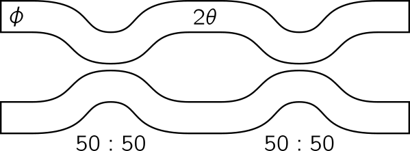
The phase shifter transfer matrices are given by,

\[ \mathbf{T}_\mathrm{ps}(\phi) = \begin{pmatrix} e^{i\phi} & 0 \\ 0 & 1 \end{pmatrix} \qquad\qquad \mathbf{T}_\mathrm{ps}(2\theta) = \begin{pmatrix} e^{i2\theta} & 0 \\ 0 & 1 \end{pmatrix}, \]

for phase shifts \(\phi\) and \(2\theta\) respectively. The directional coupler transfer matrix is given by,

\[ \mathbf{T}_\mathrm{dc}(t) = \begin{pmatrix} \sqrt{t} & i\sqrt{1-t} \\ i\sqrt{1-t} & \sqrt{t} \end{pmatrix}, \]

which simplifies to,

\[ \mathbf{T}_\mathrm{dc}(0.5) = \frac{1}{\sqrt{2}}\begin{pmatrix} 1 & i \\ i & 1 \end{pmatrix}, \]

in the ideal case of \(t = 0.5\) (i.e. 50:50). Each MZI may contribute an imbalanced probability of photon loss in each of its arms. This is modelled by multiplying a loss matrix,

\[ \mathbf{T}_\mathrm{loss}(\alpha_\mathrm{up}, \alpha_\mathrm{low}) = \begin{pmatrix} \sqrt{1 - \alpha_\mathrm{up}} & 0 \\ 0 & \sqrt{1 - \alpha_\mathrm{low}} \end{pmatrix}, \]

where \(\alpha_\mathrm{up}\), \(\alpha_\mathrm{low}\) are the fractions of light lost in the upper and lower arms of the MZI, respectively. Altogether, the MZI transfer matrix is given by,

\[ \mathbf{T}_\mathrm{mzi} = \mathbf{T}_\mathrm{loss}(\alpha_\mathrm{up}, \alpha_\mathrm{low}) \mathbf{T}_\mathrm{dc}(t_2) \mathbf{T}_\mathrm{ps}(2\theta) \mathbf{T}_\mathrm{dc}(t_1) \mathbf{T}_\mathrm{ps}(\phi) = \begin{pmatrix} \sqrt{1 - \alpha_\mathrm{up}} & 0 \\ 0 & \sqrt{1 - \alpha_\mathrm{low}} \end{pmatrix} \begin{pmatrix} \sqrt{t_2} & i\sqrt{1-t_2} \\ i\sqrt{1-t_2} & \sqrt{t_2} \end{pmatrix} \begin{pmatrix} e^{i2\theta} & 0 \\ 0 & 1 \end{pmatrix} \begin{pmatrix} \sqrt{t_1} & i\sqrt{1-t_1} \\ i\sqrt{1-t_1} & \sqrt{t_1} \end{pmatrix} \begin{pmatrix} e^{i\phi} & 0 \\ 0 & 1 \end{pmatrix}, \]

which simplifies to,

\[ \mathbf{T}_\mathrm{mzi} = \mathbf{T}_\mathrm{loss}(0, 0)\mathbf{T}_\mathrm{dc}(0.5) \mathbf{T}_\mathrm{ps}(2\theta) \mathbf{T}_\mathrm{dc}(0.5) \mathbf{T}_\mathrm{ps}(\phi) = ie^{i\theta} \begin{pmatrix} e^{i\phi}\sin{\theta} & \cos{\theta} \\ e^{i\phi}\cos{\theta} & -\sin{\theta} \end{pmatrix}, \]

in the ideal case of \(t_1 = t_2 = 0.5\), \(\alpha_\mathrm{up} = \alpha_\mathrm{low} = 0\).

Using Clements encoding, any \(m\times m\) unitary matrix can be generated by multiplying a set of block diagonal unitary transformations \(\mathbf{T}_{p,q}(\phi,\theta)\) with the \(m\times m\) identity matrix in a specific order. Each transformation, \(\mathbf{T}_{p,q}\), features a \(2\times 2\) block that acts only on adjacent modes \(p,q : p = q-1\). This \(2\times 2\) block is computed according to MZI description above. Transformations, \(\mathbf{T}_{p,q}\), are applied in each iteration of the loop. When the loop counter is even, m0 = 0 such that the transformations for the first two optical modes and each consecutive adjacent pair are generated. For example, if \(m = 5\), then the initial iteration will generate and apply \(\mathbf{ T}_{0,1}\), \(\mathbf{T}_{2,3}\), while the second iteration (m0 = 1) produces \(\mathbf{T}_{1,2}\), \(\mathbf{T}_{3,4}\). Since the phases are respectively input in 1D arrays, it must be accessed specifically when generating the transformations. Each phase shift column (\(\phi\) or \(\theta\)) requires as many phase parameters as there are transformations to generate in a given loop iteration. Thus, the input array is accessed according to the column and depends on \(m\) and m0 for the particular iteration. The matrix multiplications take place according to the order (left to right) in the figure above, Therefore, as an example, if a given iteration constructs two transformations, \(\mathbf{T}_{0,1}\) and \(\mathbf{T}_{2,3}\), the phase shifts must be ordered as \(\phi_{0,1}\), \(\phi_{2,3}\) in the array phi, and \(\theta_{0,1}\), \(\theta_{2,3}\) in the array theta.

By applying all transformations in the specified order, followed by a column of output phase shifters on each mode, a rectangular mesh that represents the full \(m \times m\) single-photon unitary matrix is generated. This is displayed below, where each cross is a MZI.
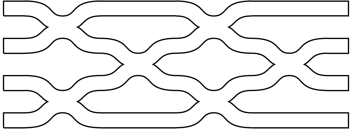

Mathematically, this procedure takes the form,

\[ \mathbf{U}(\boldsymbol{\phi}, \boldsymbol{\theta}) = \mathbf{D}\prod_{(p,q)\in R}\mathbf{T}_{p,q}(\phi,\theta), \]

where \(R\) is the sequence of the \(\frac{1}{2}m(m-1)\) two-mode transformations, \(\phi\), \(\theta\) are elements of the corresponding vectors \(\boldsymbol{\phi}\), \(\boldsymbol{\theta}\) that are selected according to the sequence, and \(\mathbf{D}\) is a diagonal \(m\times m\) matrix that is representative of the column of output phase shifters.

It is termed a "single-photon" unitary as it is a representation only in the Fock basis of \(m\) modes when \(n = 1\). To obtain the "multi-photon" unitary, a transformation must be applied (see aa).

The code in this method is heavily inspired by CasOptAx, which is properly cited at the top of the page.

Parameters:

Name Type Description Default
phi jnp_ndarray

\(m(m-1)/2\) phase shifts, \(\boldsymbol{\phi}\), for all MZIs in the mesh

required
theta jnp_ndarray

\(m(m-1)/2\) phase shifts, \(\boldsymbol{\theta}\), for all MZIs in the mesh

required
delta jnp_ndarray

\(m\) phase shifts, \(\boldsymbol{\delta}\), applied in each mode at the output of the mesh

required

Returns:

Name Type Description
U jnp_ndarray

an \(m\times m\) 2D array representative of the linear unitary transformation, \(\mathbf{U}(\boldsymbol{\phi}, \boldsymbol{\theta}, \boldsymbol{\delta})\), enacted by the Clements mesh

Source code in src/quotonic/clements.py
154
155
156
157
158
159
160
161
162
163
164
165
166
167
168
169
170
171
172
173
174
175
176
177
178
179
180
181
182
183
184
185
186
187
188
189
190
191
192
193
194
195
196
197
198
199
200
201
202
203
204
205
206
207
208
209
210
211
212
213
214
215
216
217
218
219
220
221
222
223
224
225
226
227
228
229
230
231
232
233
234
235
236
237
238
239
240
241
242
243
244
245
246
247
248
249
250
251
252
253
254
255
256
257
258
259
260
261
262
263
264
265
266
267
268
269
270
271
272
273
274
275
276
277
278
279
280
281
282
283
284
285
286
287
288
289
290
291
292
293
294
295
296
297
298
299
300
301
302
303
304
305
306
307
308
309
310
311
312
313
314
315
316
317
318
319
320
321
322
323
324
325
326
327
328
329
330
331
332
333
334
335
336
337
338
339
340
341
342
343
344
345
346
347
348
349
350
351
352
353
354
355
356
357
358
359
360
361
362
363
364
365
366
367
368
369
370
371
372
373
374
375
376
377
378
379
380
381
382
383
384
385
386
387
388
389
390
391
392
393
394
395
396
397
398
399
400
401
402
403
404
405
406
@partial(jit, static_argnums=(0,))
def encode(
    self,
    phi: jnp_ndarray,
    theta: jnp_ndarray,
    delta: jnp_ndarray,
) -> jnp_ndarray:
    """Encode a Mach-Zehnder interferometer mesh in the Clements configuration from an array of phase shifts.

    Each Mach-Zehnder interferometer (MZI), as displayed below, consists of two phase shifters enacting respective
    phase shifts $\\phi$, $\\theta$, and two directional couplers with respective splitting ratios $t_1$,
    $t_2$ (ideally, $t_1 = t_2 = 0.5$).

    <p align="center">
    <img width="500" src="../img/light/mzi.png" class="only-light">
    <img width="500" src="../img/dark/mzi.png" class="only-dark">
    </p>

    The phase shifter transfer matrices are given by,

    $$ \\mathbf{T}_\\mathrm{ps}(\\phi) = \\begin{pmatrix} e^{i\\phi} & 0 \\\\ 0 & 1 \\end{pmatrix} \\qquad\\qquad
    \\mathbf{T}_\\mathrm{ps}(2\\theta) = \\begin{pmatrix} e^{i2\\theta} & 0 \\\\ 0 & 1 \\end{pmatrix}, $$

    for phase shifts $\\phi$ and $2\\theta$ respectively. The directional coupler transfer matrix is given by,

    $$ \\mathbf{T}_\\mathrm{dc}(t) = \\begin{pmatrix} \\sqrt{t} & i\\sqrt{1-t} \\\\ i\\sqrt{1-t} & \\sqrt{t}
    \\end{pmatrix}, $$

    which simplifies to,

    $$ \\mathbf{T}_\\mathrm{dc}(0.5) = \\frac{1}{\\sqrt{2}}\\begin{pmatrix} 1 & i \\\\ i & 1 \\end{pmatrix}, $$

    in the ideal case of $t = 0.5$ (i.e. 50:50). Each MZI may contribute an imbalanced probability of photon loss
    in each of its arms. This is modelled by multiplying a loss matrix,

    $$ \\mathbf{T}_\\mathrm{loss}(\\alpha_\\mathrm{up}, \\alpha_\\mathrm{low}) = \\begin{pmatrix}
    \\sqrt{1 - \\alpha_\\mathrm{up}} & 0 \\\\ 0 & \\sqrt{1 - \\alpha_\\mathrm{low}} \\end{pmatrix}, $$

    where $\\alpha_\\mathrm{up}$, $\\alpha_\\mathrm{low}$ are the fractions of light lost in the upper and lower
    arms of the MZI, respectively. Altogether, the MZI transfer matrix is given by,

    $$ \\mathbf{T}_\\mathrm{mzi} = \\mathbf{T}_\\mathrm{loss}(\\alpha_\\mathrm{up}, \\alpha_\\mathrm{low})
    \\mathbf{T}_\\mathrm{dc}(t_2) \\mathbf{T}_\\mathrm{ps}(2\\theta) \\mathbf{T}_\\mathrm{dc}(t_1)
    \\mathbf{T}_\\mathrm{ps}(\\phi) = \\begin{pmatrix} \\sqrt{1 - \\alpha_\\mathrm{up}} & 0 \\\\ 0 & \\sqrt{1 -
    \\alpha_\\mathrm{low}} \\end{pmatrix} \\begin{pmatrix} \\sqrt{t_2} & i\\sqrt{1-t_2} \\\\ i\\sqrt{1-t_2} &
    \\sqrt{t_2} \\end{pmatrix} \\begin{pmatrix} e^{i2\\theta} & 0 \\\\ 0 & 1 \\end{pmatrix} \\begin{pmatrix}
    \\sqrt{t_1} & i\\sqrt{1-t_1} \\\\ i\\sqrt{1-t_1} & \\sqrt{t_1} \\end{pmatrix} \\begin{pmatrix} e^{i\\phi} & 0
    \\\\ 0 & 1 \\end{pmatrix}, $$

    which simplifies to,

    $$ \\mathbf{T}_\\mathrm{mzi} = \\mathbf{T}_\\mathrm{loss}(0, 0)\\mathbf{T}_\\mathrm{dc}(0.5)
    \\mathbf{T}_\\mathrm{ps}(2\\theta) \\mathbf{T}_\\mathrm{dc}(0.5) \\mathbf{T}_\\mathrm{ps}(\\phi) =
    ie^{i\\theta} \\begin{pmatrix} e^{i\\phi}\\sin{\\theta} & \\cos{\\theta} \\\\ e^{i\\phi}\\cos{\\theta} &
    -\\sin{\\theta} \\end{pmatrix}, $$

    in the ideal case of $t_1 = t_2 = 0.5$, $\\alpha_\\mathrm{up} = \\alpha_\\mathrm{low} = 0$.

    Using Clements encoding, any $m\\times m$ unitary matrix can be generated by multiplying a set of block
    diagonal unitary transformations $\\mathbf{T}_{p,q}(\\phi,\\theta)$ with the $m\\times m$ identity matrix in a
    specific order. Each transformation, $\\mathbf{T}_{p,q}$, features a $2\\times 2$ block that acts only on
    adjacent modes $p,q : p = q-1$. This $2\\times 2$ block is computed according to MZI description above.
    Transformations, $\\mathbf{T}_{p,q}$, are applied in each iteration of the loop. When the loop counter is
    even, `m0 = 0` such that the transformations for the first two optical modes and each consecutive adjacent
    pair are generated. For example, if $m = 5$, then the initial iteration will generate and apply $\\mathbf{
    T}_{0,1}$, $\\mathbf{T}_{2,3}$, while the second iteration (`m0 = 1`) produces $\\mathbf{T}_{1,2}$,
    $\\mathbf{T}_{3,4}$. Since the phases are respectively input in 1D arrays, it must be accessed specifically
    when generating the transformations. Each phase shift column ($\\phi$ or $\\theta$) requires as many phase
    parameters as there are transformations to generate in a given loop iteration. Thus, the input array is
    accessed according to the column and depends on $m$ and `m0` for the particular iteration. The matrix
    multiplications take place according to the order (left to right) in the figure above, Therefore,
    as an example, if a given iteration constructs two transformations, $\\mathbf{T}_{0,1}$ and
    $\\mathbf{T}_{2,3}$, the phase shifts must be ordered as $\\phi_{0,1}$, $\\phi_{2,3}$ in the array
    `phi`, and $\\theta_{0,1}$, $\\theta_{2,3}$ in the array `theta`.

    By applying all transformations in the specified order, followed by a column of output phase shifters on
    each mode, a rectangular mesh that represents the full $m \\times m$ single-photon unitary matrix is
    generated. This is displayed below, where each cross is a MZI.

    <p align="center">
    <img width="500" src="../img/light/mesh.png" class="only-light">
    <img width="500" src="../img/dark/mesh.png" class="only-dark">
    </p>

    Mathematically, this procedure takes the form,

    $$ \\mathbf{U}(\\boldsymbol{\\phi}, \\boldsymbol{\\theta}) =
    \\mathbf{D}\\prod_{(p,q)\\in R}\\mathbf{T}_{p,q}(\\phi,\\theta), $$

    where $R$ is the sequence of the $\\frac{1}{2}m(m-1)$ two-mode transformations, $\\phi$, $\\theta$ are
    elements of the corresponding vectors $\\boldsymbol{\\phi}$, $\\boldsymbol{\\theta}$ that are selected
    according to the sequence, and $\\mathbf{D}$ is a diagonal $m\\times m$ matrix that is representative of the
    column of output phase shifters.

    It is termed a "single-photon" unitary as it is a representation only in the Fock basis of $m$ modes when $n
    = 1$. To obtain the "multi-photon" unitary, a transformation must be applied (see [aa](aa.md)).

    The code in this method is heavily inspired by [CasOptAx](https://github.com/JasvithBasani/CasOptAx), which is
    properly cited at the top of the page.

    Args:
        phi: $m(m-1)/2$ phase shifts, $\\boldsymbol{\\phi}$, for all MZIs in the mesh
        theta: $m(m-1)/2$ phase shifts, $\\boldsymbol{\\theta}$, for all MZIs in the mesh
        delta: $m$ phase shifts, $\\boldsymbol{\\delta}$, applied in each mode at the output of the mesh

    Returns:
        U: an $m\\times m$ 2D array representative of the linear unitary transformation,
            $\\mathbf{U}(\\boldsymbol{\\phi}, \\boldsymbol{\\theta}, \\boldsymbol{\\delta})$, enacted by the
            Clements mesh
    """

    # check the validity of the mesh and the provided phases
    assert self.m > 2, "Clements encoding is only relevant for m > 2, see 'mzi' otherwise"
    assert len(phi) == int(self.m * (self.m - 1) / 2), "There must be exactly m(m-1)/2 phi phase shifts"
    assert len(theta) == int(self.m * (self.m - 1) / 2), "There must be exactly m(m-1)/2 theta phase shifts"
    assert len(delta) == int(self.m), "There must be exactly m delta phase shifts"

    # ensure that the provided phases are jax arrays
    phi = jnp.asarray(phi)
    theta = jnp.asarray(theta)
    delta = jnp.asarray(delta)

    # iterate through each column of the mesh, constructing and multiplying the transformations for each MZI
    ind = 0
    m_2 = self.m // 2
    odd = self.m % 2  # equals 0 if even, 1 if odd
    even = (self.m + 1) % 2  # equals 0 if odd, 1 if even
    columns = []
    for col in range(self.m):
        # calculate whether MZIs should be inserted from mode 0 or mode 1
        m0 = col % 2

        # extract the parameters for the MZIs in this column
        theta_col = theta[ind : ind + m_2 - m0 * even]
        phi_col = phi[ind : ind + m_2 - m0 * even]
        t_dc_col = self.t_dc[:, ind : ind + m_2 - m0 * even]
        ind += m_2 - m0 * even

        # construct matrices that describe the transformations enacted by two full columns of T:R
        # directional couplers, nominally 50:50
        dc_diag = jnp.diag(
            jnp.pad(
                jnp.repeat(jnp.sqrt(t_dc_col[0]), 2),
                (m0, (m0 + odd) % 2),
                "constant",
                constant_values=(1.0, 1.0),
            )
        )
        dc_offdiag_up = jnp.roll(
            jnp.diag(
                jnp.pad(
                    jnp.dstack(
                        (1j * jnp.sqrt(1.0 - t_dc_col[0]), jnp.zeros(m_2 - m0 * even, dtype=complex))
                    ).flatten(),
                    (m0, (m0 + odd) % 2),
                    "constant",
                    constant_values=(0.0, 0.0),
                )
            ),
            1,
        )
        dc_offdiag_down = jnp.roll(
            jnp.diag(
                jnp.pad(
                    jnp.dstack(
                        (jnp.zeros(m_2 - m0 * even, dtype=complex), 1j * jnp.sqrt(1.0 - t_dc_col[0]))
                    ).flatten(),
                    (m0, (m0 + odd) % 2),
                    "constant",
                    constant_values=(0.0, 0.0),
                )
            ),
            -1,
        )
        dc1 = dc_diag + dc_offdiag_up + dc_offdiag_down

        dc_diag = jnp.diag(
            jnp.pad(
                jnp.repeat(jnp.sqrt(t_dc_col[1]), 2),
                (m0, (m0 + odd) % 2),
                "constant",
                constant_values=(1.0, 1.0),
            )
        )
        dc_offdiag_up = jnp.roll(
            jnp.diag(
                jnp.pad(
                    jnp.dstack(
                        (1j * jnp.sqrt(1.0 - t_dc_col[1]), jnp.zeros(m_2 - m0 * even, dtype=complex))
                    ).flatten(),
                    (m0, (m0 + odd) % 2),
                    "constant",
                    constant_values=(0.0, 0.0),
                )
            ),
            1,
        )
        dc_offdiag_down = jnp.roll(
            jnp.diag(
                jnp.pad(
                    jnp.dstack(
                        (jnp.zeros(m_2 - m0 * even, dtype=complex), 1j * jnp.sqrt(1.0 - t_dc_col[1]))
                    ).flatten(),
                    (m0, (m0 + odd) % 2),
                    "constant",
                    constant_values=(0.0, 0.0),
                )
            ),
            -1,
        )
        dc2 = dc_diag + dc_offdiag_up + dc_offdiag_down

        # construct matrices that describe the transformations enacted by full columns of
        # phi & 2theta phase shifters respectively
        ps_phi = jnp.diag(
            jnp.pad(
                jnp.dstack((jnp.exp(1j * phi_col), jnp.ones(m_2 - m0 * even, dtype=complex))).reshape(
                    self.m - odd - 2 * m0 * even
                ),
                (m0, (m0 + odd) % 2),
                "constant",
                constant_values=(1.0, 1.0),
            )
        )
        ps_2theta = jnp.diag(
            jnp.pad(
                jnp.dstack((jnp.exp(2j * theta_col), jnp.ones(m_2 - m0 * even, dtype=complex))).reshape(
                    self.m - odd - 2 * m0 * even
                ),
                (m0, (m0 + odd) % 2),
                "constant",
                constant_values=(1.0, 1.0),
            )
        )

        # construct matrix the describes the loss per arm of the interferometer mesh for this column
        loss = jnp.diag(jnp.sqrt(1.0 - self.ell_mzi[:, col]))

        # multiply each component of the MZI together to form the full transformation from this column
        column = loss @ dc2 @ ps_2theta @ dc1 @ ps_phi

        # add to list of column matrices that will multiply together at the end
        columns.append(column)

    # construct matrix that describes the transformation enacted by the output phase shifters in each mode
    ps_delta = jnp.diag(jnp.exp(1j * delta))

    # construct matrix that describes the loss per output phase shifter
    loss = jnp.diag(jnp.sqrt(1.0 - self.ell_ps))

    # multiply all the columns, followed by the output phase shifters, to construct the full mesh transformation
    U = loss @ ps_delta @ reduce(jnp.matmul, columns[::-1])
    return U

decode(U)

Perform Clements decomposition on a square \(m\times m\) unitary matrix.

Given some linear \(m\times m\) unitary transformation, where \(m\) is the number of optical modes, this method performs Clements decomposition to determine the phase shifts (\(\phi, \theta\)) for each MZI such that the mesh performs this transformation. For more details on the decomposition procedure, see W. R. Clements et al., "Optimal design for universal multiport interferometers", Optica 3, 1460-1465 (2016). This method is adapted from the Interferometer repository.

The main difference between this implementation and the original by Clements et al. is the form of the MZI transfer matrix assumed. In the ideal case, a MZI is described by,

\[ ie^{i\theta}\begin{pmatrix} e^{i\phi}\sin{\theta} & \cos{\theta} \\ e^{i\phi}\cos{\theta} & -\sin{\theta} \end{pmatrix}. \]

Clements et al. chose to perform a transformation, \(\theta\to\frac{\pi}{2}-\theta\), \(\phi\to\phi+\pi\), to achieve the form,

\[ e^{-i\theta}\begin{pmatrix} e^{i\phi}\cos{\theta} & -\sin{\theta} \\ e^{i\phi}\sin{\theta} & \cos{\theta} \end{pmatrix}. \]

Here, this transformation is undone by applying the inverse transformation, \(\theta\to\frac{\pi}{ 2}-\theta\), \(\phi\to\phi+\pi\), at each stage of the decomposition procedure. This function concludes by arranging the phase shifts as required for the encoding scheme specified in encode.

Parameters:

Name Type Description Default
U np_ndarray

\(m\times m\) unitary matrix, \(\mathbf{U}(\boldsymbol{\phi}, \boldsymbol{\theta}, \boldsymbol{\delta})\), to perform Clements decomposition on

required

Returns:

Name Type Description
phi np_ndarray

array of \(m(m-1)/2\) phase shifts, \(\boldsymbol{\phi}\), for all MZIs in the mesh

theta np_ndarray

array of \(m(m-1)/2\) phase shifts, \(\boldsymbol{\theta}\), for all MZIs in the mesh

delta np_ndarray

array of \(m\) phase shifts, \(\boldsymbol{\delta}\), applied in each mode at the output of the mesh

Source code in src/quotonic/clements.py
408
409
410
411
412
413
414
415
416
417
418
419
420
421
422
423
424
425
426
427
428
429
430
431
432
433
434
435
436
437
438
439
440
441
442
443
444
445
446
447
448
449
450
451
452
453
454
455
456
457
458
459
460
461
462
463
464
465
466
467
468
469
470
471
472
473
474
475
476
477
478
479
480
481
482
483
484
485
486
487
488
489
490
491
492
493
494
495
496
497
498
499
500
501
502
503
504
505
506
507
508
509
510
511
512
513
514
515
516
517
518
519
520
521
522
523
524
525
526
527
528
529
530
531
532
533
534
535
536
537
538
539
540
541
542
543
544
545
546
547
548
549
550
551
552
553
554
555
556
557
def decode(self, U: np_ndarray) -> tuple[np_ndarray, np_ndarray, np_ndarray]:
    """Perform Clements decomposition on a square $m\\times m$ unitary matrix.

    Given some linear $m\\times m$ unitary transformation, where $m$ is the number of optical modes, this method
    performs Clements decomposition to determine the phase shifts ($\\phi, \\theta$) for each MZI such that the
    mesh performs this transformation. For more details on the decomposition procedure, see [W. R. Clements *et
    al*., "Optimal design for universal multiport interferometers", *Optica* **3**, 1460-1465 (2016)](
    https://doi.org/10.1364/OPTICA.3.001460). This method is adapted from the [Interferometer](
    https://github.com/clementsw/interferometer) repository.

    The main difference between this implementation and the original by Clements *et al*. is the form of the MZI
    transfer matrix assumed. In the ideal case, a MZI is described by,

    $$ ie^{i\\theta}\\begin{pmatrix} e^{i\\phi}\\sin{\\theta} & \\cos{\\theta} \\\\ e^{i\\phi}\\cos{\\theta} &
    -\\sin{\\theta} \\end{pmatrix}. $$

    Clements *et al*. chose to perform a transformation, $\\theta\\to\\frac{\\pi}{2}-\\theta$,
    $\\phi\\to\\phi+\\pi$, to achieve the form,

    $$ e^{-i\\theta}\\begin{pmatrix} e^{i\\phi}\\cos{\\theta} & -\\sin{\\theta} \\\\ e^{i\\phi}\\sin{\\theta} &
    \\cos{\\theta} \\end{pmatrix}. $$

    Here, this transformation is undone by applying the inverse transformation, $\\theta\\to\\frac{\\pi}{
    2}-\\theta$, $\\phi\\to\\phi+\\pi$, at each stage of the decomposition procedure. This function concludes by
    arranging the phase shifts as required for the encoding scheme specified in `encode`.

    Args:
        U: $m\\times m$ unitary matrix, $\\mathbf{U}(\\boldsymbol{\\phi}, \\boldsymbol{\\theta},
            \\boldsymbol{\\delta})$, to perform Clements decomposition on

    Returns:
        phi: array of $m(m-1)/2$ phase shifts, $\\boldsymbol{\\phi}$, for all MZIs in the mesh
        theta: array of $m(m-1)/2$ phase shifts, $\\boldsymbol{\\theta}$, for all MZIs in the mesh
        delta: array of $m$ phase shifts, $\\boldsymbol{\\delta}$, applied in each mode at the output of the mesh
    """

    # check that U is m x m
    assert len(U.shape) == 2, "Unitary matrix must be a 2D array"
    assert U.shape[0] == self.m, "Unitary matrix must be m x m"
    assert U.shape[1] == self.m, "Unitary matrix must be m x m"

    # initialize lists of MZIs and T_{p,q} applied from the left
    MZIs = []
    T_lefts = []

    # need to zero out m - 1 diagonal sections from the matrix U
    for i in range(self.m - 1):
        # for even i, multiply from the right
        if i % 2 == 0:
            for j in range(i + 1):
                # store modes that T acts on
                p = i - j
                q = i - j + 1

                # compute phi, theta to 0 out matrix element
                phi = (
                    np.pi
                    if U[self.m - j - 1, i - j + 1] == 0
                    else np.pi + np.angle(U[self.m - j - 1, i - j] / U[self.m - j - 1, i - j + 1])
                )
                theta = np.pi / 2 - np.arctan2(
                    np.abs(U[self.m - j - 1, i - j]), np.abs(U[self.m - j - 1, i - j + 1])
                )

                # from phi, theta, construct T_{p,q}^{-1}, then right-multiply
                T_right = np.eye(self.m, dtype=complex)
                T_right[p : q + 1, p : q + 1] = self.mzi_inv(phi, theta)
                U = np.dot(U, T_right)

                # append MZI to list, noting modes and phases
                MZIs.append({"pq": (p, q), "phi": phi, "theta": theta})

        # for odd i, multiply from the left
        else:
            for j in range(i + 1):
                # store modes that T acts on
                p = self.m + j - i - 2
                q = self.m + j - i - 1

                # compute phi, theta to 0 out matrix element
                phi = (
                    np.pi
                    if U[self.m + j - i - 2, j] == 0
                    else np.pi + np.angle(-U[self.m + j - i - 1, j] / U[self.m + j - i - 2, j])
                )
                theta = np.pi / 2 - np.arctan2(np.abs(U[self.m + j - i - 1, j]), np.abs(U[self.m + j - i - 2, j]))

                # from phi, theta, construct T_{p,q}, then left-multiply
                T_left = np.eye(self.m, dtype=complex)
                T_left[p : q + 1, p : q + 1] = self.mzi(phi, theta)
                U = np.dot(T_left, U)

                # append left-multiplying T_{p,q} to list, noting modes and phases
                T_lefts.append({"pq": (p, q), "phi": phi, "theta": theta})

    # check that the resultant matrix, $D$, is diagonal
    assert np.allclose(np.abs(np.diag(U)), np.ones(self.m)), "Decomposition did not yield a diagonal matrix D"

    # rearrange the transformations to match the encoding scheme
    for T in reversed(T_lefts):
        # extract modes, phases for the T_{p,q}
        p, q = T["pq"]
        phi = T["phi"]
        theta = T["theta"]

        # construct T_{p,q}^{-1}, then left-multiply
        T_left_inv = np.eye(self.m, dtype=complex)
        T_left_inv[p : q + 1, p : q + 1] = self.mzi_inv(phi, theta)
        U = np.dot(T_left_inv, U)

        # compute phi, theta that allow T_{p,q}^{-1} to be multiplied on the right
        phi = np.pi if U[q, q] == 0 else np.pi + np.angle(U[q, p] / U[q, q])
        theta = np.pi / 2 - np.arctan2(np.abs(U[q, p]), np.abs(U[q, q]))

        # from phi, theta, construct T_{p,q}^{-1}, then right-multiply
        T_right = np.eye(self.m, dtype=complex)
        T_right[p : q + 1, p : q + 1] = self.mzi_inv(phi, theta)
        U = np.dot(U, T_right)

        # append MZI to list, noting modes and phases
        MZIs.append({"pq": (p, q), "phi": phi, "theta": theta})

    # check that the resultant matrix, $D'$, is diagonal
    assert np.allclose(np.abs(np.diag(U)), np.ones(self.m)), "Decomposition did not yield a diagonal matrix D'"

    # compute output phases from the diagonal of the resultant matrix U
    delta = np.angle(np.diag(U))

    # sort the MZIs by mode pair and the order in which they must be applied
    sorted_MZIs: list = [[] for _ in range(self.m - 1)]
    for MZI in MZIs:
        sorted_MZIs[MZI["pq"][0]].append(MZI)

    # extract the phi, theta phase shifts from the sorted MZIs in the correct order
    phi = np.zeros(int(self.m * (self.m - 1) / 2))
    theta = np.zeros(int(self.m * (self.m - 1) / 2))

    indp = 0
    indt = 0
    for i in range(self.m):
        m0 = i % 2
        for j in range(m0, self.m - 1, 2):
            MZI = sorted_MZIs[j].pop(0)
            phi[indp] = MZI["phi"]
            theta[indt] = MZI["theta"]

            indp += 1
            indt += 1

    return phi, theta, delta